| app | ||
| static | ||
| Arburg.svg | ||
| ARBURG_zones.svg | ||
| doors-connector.md | ||
| readme.md | ||
| shematic.svg | ||
| Thermoplay.svg | ||
| unnamed.png | ||
| unnamed1.jpg | ||
Arburg ↔ Thermoplay Hot Runner Wiring

Proportional regulator / Hot runner interface wiring documentation
Date: 11.11.2023
Overview
This document describes the wiring between the Arburg machine connectors and the Thermoplay hot runner connector.
⚠️ Important: Heater zone pinouts and J-type thermocouple (TC) pinouts use different pin assignments on each side.
Thermoplay Connector Pinout (M / F)
| Connector | Part number + comment |
|---|---|
| 09330242601 | Han E 24 Pos. M Insert Screw |
| 09330242701 | Han E 24 Pos. F Insert Screw |

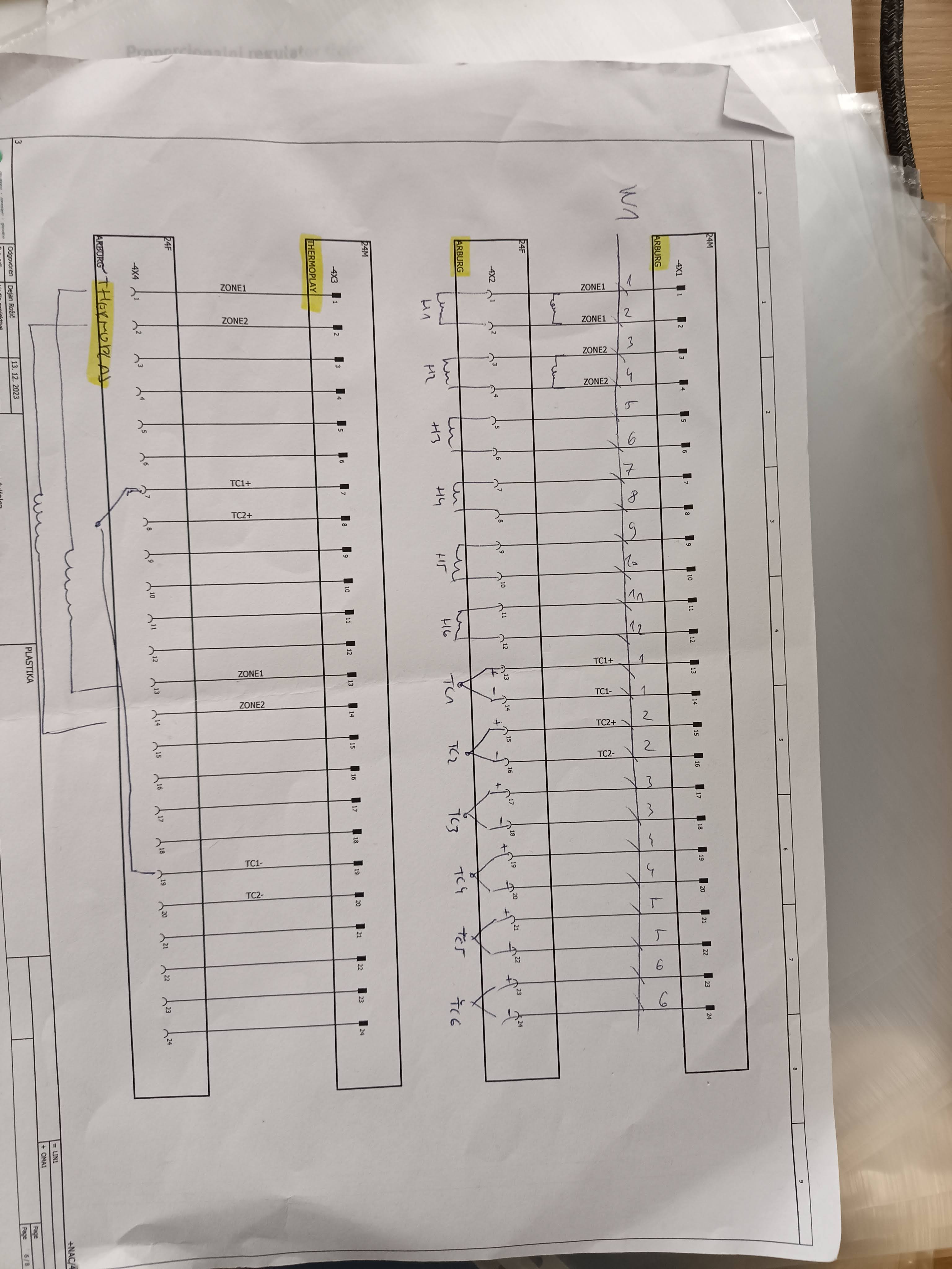
 From the Thermoplay connector label (Image 2):
| Function | M-side Pin (+) | F-side Pin (-) |
|---|---|---|
| ZONE 1 | 1 | 13 |
| ZONE 2 | 2 | 14 |
| ZONE 3 | 3 | 15 |
| ZONE 4 | 4 | 16 |
| ZONE 5 | 5 | 17 |
| ZONE 6 | 6 | 18 |
| TC 1 | 7 (+) | 19 (−) |
| TC 2 | 8 (+) | 20 (−) |
| TC 3 | 9 (+) | 21 (−) |
| TC 4 | 10 (+) | 22 (−) |
| TC 5 | 11 (+) | 23 (−) |
| TC 6 | 12 (+) | 24 (−) |
Arburg Machine Connector Pinout
Heater Zones (connectors -4X4 / -4X2)
| Arburg Zone | Pin (L) | Pin (N) |
|---|---|---|
| Heater 1 | 1 | 2 |
| Heater 2 | 3 | 4 |
| Heater 3 | 5 | 6 |
| Heater 4 | 7 | 8 |
| Heater 5 | 9 | 10 |
| Heater 6 | 11 | 12 |
Each heater zone uses a pair of adjacent pins.
Thermocouple Inputs —
| Arburg TC | Pin (+) | Pin (−) |
|---|---|---|
| TC 1 | 13 | 14 |
| TC 2 | 15 | 16 |
| TC 3 | 17 | 18 |
| TC 4 | 19 | 20 |
| TC 5 | 21 | 22 |
| TC 6 | 23 | 24 |
TC signals are J-type thermocouples. Polarity must be respected — reversed polarity will cause incorrect temperature readings.
Cross-Wiring Table: Arburg → Thermoplay
| Signal | Arburg Pin | Thermoplay Pin |
|---|---|---|
| Zone 1 + | 1 | 1 |
| Zone 1 − | 2 | 13 |
| Zone 2 + | 3 | 2 |
| Zone 2 − | 4 | 14 |
| Zone 3 + | 5 | 3 |
| Zone 3 − | 6 | 15 |
| Zone 4 + | 7 | 4 |
| Zone 4 − | 8 | 16 |
| Zone 5 + | 9 | 5 |
| Zone 5 − | 10 | 17 |
| Zone 6 + | 11 | 6 |
| Zone 6 − | 12 | 18 |
| TC 1 + | 13 | 7 |
| TC 1 − | 14 | 19 |
| TC 2 + | 15 | 8 |
| TC 2 − | 16 | 20 |
| TC 3 + | 17 | 9 |
| TC 3 − | 18 | 21 |
| TC 4 + | 19 | 10 |
| TC 4 − | 20 | 22 |
| TC 5 + | 21 | 11 |
| TC 5 − | 22 | 23 |
| TC 6 + | 23 | 12 |
| TC 6 − | 24 | 24 |
Key Differences — Arburg vs Thermoplay
| Property | Arburg Side | Thermoplay Side |
|---|---|---|
| Heater pair logic | Adjacent pins (1+2, 3+4, …) | Split across M/F halves (1/13, 2/14, …) |
| TC logic | Sequential pairs (13+14, 15+16, …) | Offset by 12 pins (7/19, 8/20, …) |
| TC type | J-type | J-type |
| Zones supported | Up to 6 | Up to 6 |
Thermocouple + Heater Connection Diagram
Connection scheme for a typical dual-zone heating system with two heaters and two thermocouples (usually type K).
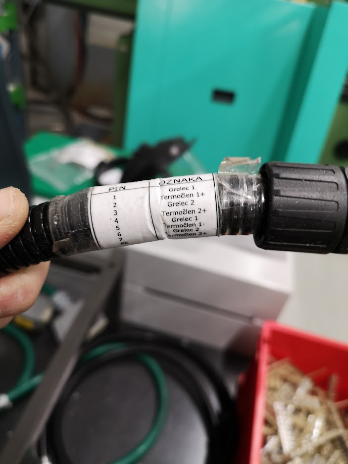
Pinout / Terminal Layout - 8PIN connector 7+PE
| Connector | Part number + comment |
|---|---|
| 09 36 008 2632 | Han 8D-M Quick Lock 1,5mm² |
| 09 36 008 2732 | Han 8D-F Quick Lock 1,5mm² |
| PIN | OZNAKA / Signal | Description | Typical Wire Color (Type K) |
|---|---|---|---|
| 1 | Grelec 1 | Heater 1 – Live / Phase | – |
| 2 | Termočlen 1+ | Thermocouple 1 – Positive | Yellow / Green |
| 3 | Grelec 2 | Heater 2 – Live / Phase | – |
| 4 | Termočlen 2 + | Thermocouple 2 – Positive | Yellow / Green |
| 5 | Grelec 1 | Heater 1 – Neutral / Return | – |
| 6 | Termočlen 1- | Thermocouple 1 – Negative | White / Red |
| 7 | Grelec 2 | Heater 2 – Neutral / Return | – |
| 8/PE | Termočlen 2- | Thermocouple 2 – Negative | White / Red |
Notes:
- Pins 1 & 5 → Heater 1 (usually 230 V AC or 24 V, depending on system)
- Pins 3 & 7 → Heater 2
- Pins 2 & 6 → Thermocouple 1 (most likely type K)
- Pins 4 & 8 → Thermocouple 2 (most likely type K)
- Pin 8 is often marked as PE on the connector, but in this case it is used as TC2– (negative leg of the second thermocouple)
Wiring Recommendations
- Use compensating cable (type K compensation) or true thermocouple extension wire for pins 2,4,6,8
- Never use ordinary copper wire for thermocouple connections → causes large measurement error
- Heater wires (1,3,5,7) – use appropriate cross-section according to current (usually 0.75–2.5 mm²)
- Recommended tightening torque: usually 0.5–0.6 Nm (check connector specification)
Visual connection scheme (text version)
Notes
- Always verify wiring with a multimeter before powering up.
- Mislabelled or swapped TC wires will cause temperature runaway or zone shutdown.
- Heater zones carry mains voltage — ensure the machine is locked out before working on wiring.
Document generated from Arburg proportional regulator schematic & Thermoplay connector diagram.